
Integral welded frame
Integral welded frame construction with minimal deformation, suited for precision continuous mould processing.
JW31
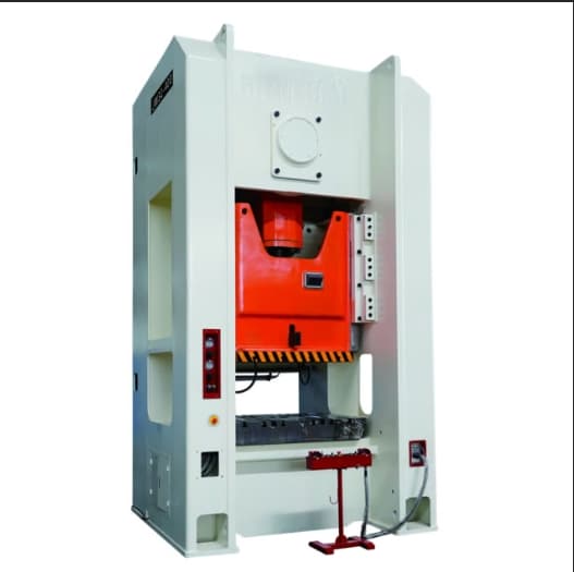
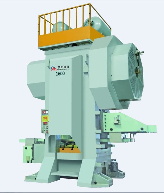
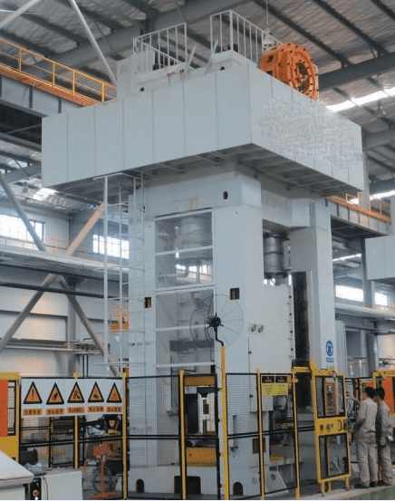
A closed-frame single-point mechanical press with double-crankshaft reverse transmission and anti-eccentric-load guide rails, delivering high precision and resistance to off-center loads.
Overview
The JW31 series closed single-point press employs double crankshaft reverse transmission and anti-eccentric load guide rails, which improves the machine tool’s anti-eccentric load capability.
The slide features four-corner eight-sided long guide rails, which give good guidance and high precision.
Key data
Full technical parameters are confirmed together with our engineers, based on your part and production volume.
Features
Integral welded frame construction with minimal deformation, suited for precision continuous mould processing.
Four-corner eight-sided long guide rails providing superior guidance and precision while resisting off-centre loading.
High-torque wet friction clutch offering stable operation, low noise and extended service life.
Electric mould adjustment with accuracy to 0.1 mm.
Centralized lubrication system with cycle indicator.
Advanced multi-functional electronic control system emphasizing safety.
Compatible with various automation equipment to enhance productivity.
In use
Gallery
| Parameter | Unit | JW31-160 S | JW31-160 H | JW31-200 S | JW31-200 H | JW31-250 S | JW31-250 H | JW31-315 S | JW31-315 H | JW31-400 S | JW31-400 H | JW31-500 | JW31-630 | JW31-800 |
|---|---|---|---|---|---|---|---|---|---|---|---|---|---|---|
| Nominal pressure | kN | 1600 | 1600 | 2000 | 2000 | 2500 | 2500 | 3150 | 3150 | 4000 | 4000 | 5000 | 6300 | 8000 |
| Nominal stroke | mm | 6 | 6 | 6 | 6 | 6,5 | 6,5 | 7 | 7 | 8 | 8 | 8 | 10 | 10 |
| Slide stroke | mm | 180 | 130 | 200 | 150 | 220 | 160 | 220 | 160 | 250 | 180 | 250 | 250 | 250 |
| Slide strokes per minute — fixed | min⁻¹ | 45 | 60 | 45 | 50 | 30 | 45 | 30 | 45 | 25 | 35 | 20 | 20 | 15 |
| Slide strokes per minute — variable | min⁻¹ | 35–55 | 50–70 | 35–55 | 40–60 | 20–35 | 30–55 | 20–35 | 30–55 | 20–30 | 30–40 | 15–25 | 15–25 | 12–18 |
| Max. die set height | mm | 400 | 425 | 450 | 475 | 500 | 530 | 550 | 580 | 600 | 635 | 650 | 650 | 700 |
| Die height adjustment | mm | 110 | 110 | 110 | 110 | 120 | 120 | 120 | 120 | 120 | 120 | 120 | 120 | 120 |
| Distance between uprights | mm | 1100 | 1100 | 1200 | 1200 | 1300 | 1300 | 1350 | 1350 | 1450 | 1450 | 1650 | 1850 | 2050 |
| Slide bottom size | mm | 750×600 | 750×600 | 850×700 | 850×700 | 950×750 | 950×750 | 1000×800 | 1000×800 | 1100×850 | 1100×850 | 1250×950 | 1400×1200 | 1600×1200 |
| Shank hole size | mm | φ65×90 | φ65×90 | φ65×90 | φ65×90 | φ70×95 | φ70×95 | φ70×95 | φ70×95 | φ80×100 | φ80×100 | φ80×100 | φ80×110 | φ80×120 |
| Bolster size | mm | 1000×650 | 1000×650 | 1100×750 | 1100×750 | 1200×800 | 1200×800 | 1250×850 | 1250×850 | 1350×900 | 1350×900 | 1500×1000 | 1700×1200 | 1800×1300 |
| Blanking hole diameter | mm | φ180 | φ180 | φ200 | φ200 | φ200 | φ200 | φ220 | φ220 | φ220 | φ220 | φ220 | φ220 | φ220 |
| Bolster thickness | mm | 165 | 165 | 180 | 180 | 190 | 190 | 190 | 190 | 200 | 200 | 220 | 220 | 240 |
| Bolster surface height | mm | 900 | 900 | 985 | 985 | 1080 | 1080 | 1075 | 1075 | 1090 | 1090 | 1090 | 1260 | 1260 |
| Dimensions of side opening | mm | 650×350 | 650×350 | 750×420 | 750×420 | 800×430 | 800×430 | 850×480 | 850×480 | 900×520 | 900×520 | 1000×650 | 1100×650 | 1200×700 |
| Motor power | kW | 15 | 15 | 18,5 | 18,5 | 22 | 22 | 30 | 30 | 37 | 37 | 45 | 75 | 75 |
| Overall dimensions | mm | 2300×1820×3710 | 2300×1820×3710 | 2370×2080×4220 | 2370×2080×4220 | 2480×2200×4560 | 2480×2200×4560 | 2600×2260×4610 | 2600×2260×4610 | 2690×2480×4960 | 2690×2480×4960 | 2880×2700×5420 | 4000×2780×6100 | 3900×3060×6200 |
| Press pressure | MPa | 0,5 | 0,5 | 0,5 | 0,5 | 0,5 | 0,5 | 0,5 | 0,5 | 0,5 | 0,5 | 0,5 | 0,5 | 0,5 |
* Specifications shown correspond to the reference model in each series and may vary by configuration.
Advantages
From billet handling and ring rolling to shearing, descaling and final pressing — 15 distinct machines cover virtually every complementary stage of the forging workflow.
01Every machine is designed to run standalone or integrated, alongside Anyang CNC hammers and presses, into fully automated production lines.
02Technologies such as ring rolling and cross wedge rolling reduce material waste and improve dimensional accuracy compared with conventional cutting or free-forging methods.
03Welded steel frames, PLC/CNC control and reliable hydraulic or pneumatic systems, built for continuous, multi-shift operation.
04See also
 D53K
D53K D51
D51
 WGP
WGP JH21
JH21 ZGD
ZGD
 JS31
JS31 X-Q45
X-Q45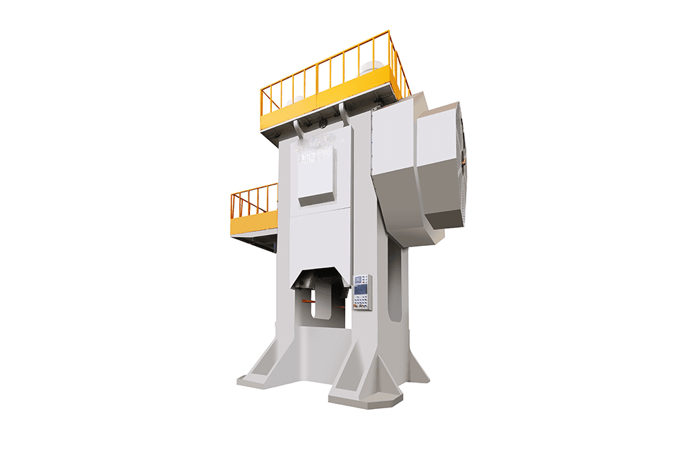 WP
WPOur technical team helps you identify the right equipment from this extensive portfolio, for any stage of your forging workflow.